Products · Products · Products · Products · Products · Products · Products · Products · Products · Products · Products · Products · Products · Products · Products · Products ·
SFP Optical Module

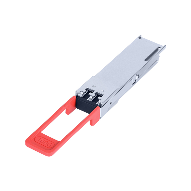
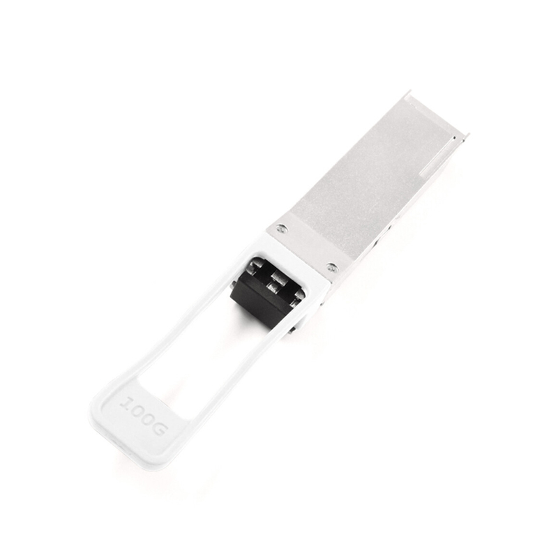
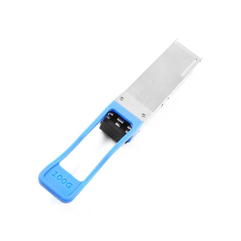
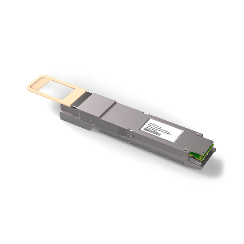
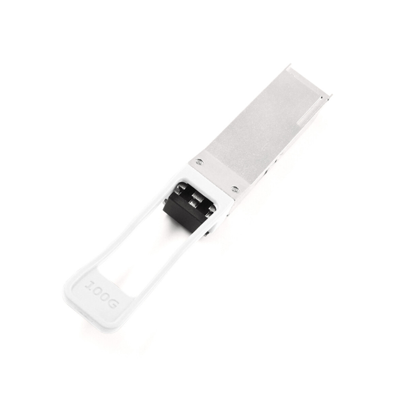
Home · Products · SFP Optical Module · 100G ZR4 Long Reach Transceiver QSFP28 100km
  • Product Details

Absolute Maximum Ratings
It has to be noted that the operation in excess of any individual absolute maximum ratings might cause permanent damage to this transceiver.

Parameter
Symbol
Min
Typ
Max
Unit
Notes
Maximum Supply Voltage
Vcc
0
3.6
V
Storage Temperature
Ts
-40
85
℃
Relative Humidity
RH
5
85
%
1
Damage Threshold, each lane
THd
6.5
dBm
Notes: Non‑condensing.

Operating Environment
Electrical and optical characteristics below are defined under this operating environment, unless otherwise specified.
Parameter
Symbol
Min
Typ
Max
Unit
Supply Voltage
Vcc
3.135
3.3
3.465
V
Case Temperature
Top
0
70
℃
Link Distance with G.652
100
km

Electrical Characteristics
Parameter Symbol Min Typ Max Unit Note
Power dissipation 6.5 W
Supply Current Icc 1.8759 A Steady state
Transmitter
Data Rate, each lane 25.78125 Gbps
Differential Voltage pk-pk Vpp 900 mV At 1 MHz
Common Mode Voltage Vcm -350 2850 mV
Transition time Trise/Tfall 10 ps 20%~80%
Differential Termination Resistance Mismatch 10 %
Eye width EW15 0.46 UI
Eye height EH15 95 mV
Receiver
Data Rate, each lane 25.78125 Gbps
Differential Termination Resistance Mismatch 10 % At 1 MHz
Differential output voltage swing Vout, pp 900 mV
Common Mode Noise, RMS Vrms 17.5 mV
Transition time Trise/Tfall 12 ps 20%~80%
Eye width EW15 0.57 UI
Eye height EH15 228 mV

Optical Characteristics
Parameters Unit min type max Note
Transmitter
Signaling Speed per Lane Gb/s 25.78125 ± 100 ppm
Transmit wavelengths nm 1294.53 1299.02 1303.54 1308.09 1295.56 1300.05 1304.58 1309.14 1296.59 1301.09 1305.63 1310.19
Side‑Mode Suppression Ratio (SMSR) dB 30
Total Average Launch Power dBm 8 12.5
Average launch power, each lane dBm 2 6.5
Difference in launch power between any two lanes(Average and OMA) dBm 3
Average launch power of OFF transmitter, each lane dBm -30
Extinction Ratio (ER) dB 6
RIN OMA dB/Hz -130
Optical return loss tolerance dB 20
Transmitter reflectance dB -12
Transmitter eye mask definition (X1, {0.25, 0.4, 0.45, 0.25, 0.28, 0.4} 1
{X2, X3, Y1, Y2, Y3}
Mask margin % 5
Receiver
Signaling Speed per Lane Gb/s 25.78125 ±100 ppm
Receive wavelengths nm 1294.53 1299.02 1303.54 1308.09 1295.56 1300.05 1304.58 1309.14 1296.59 1301.09 1305.63 1310.19
Average receiver power, each lane dBm -29 -7
Receiver power, each lane(OMA) dBm -7
Receiver reflectance dB -27
Receiver sensitivity Average, each lane dBm -28 1
Receiver 3 dB electrical upper cutoff frequency, each lane GHz 31
Damage threshold, each lane dBm 6.5
LOS Assert dBm -40
LOS Deassert dBm -29
LOS Hysteresis dB 0.5
Notes: Sensitivity is specified at BER@2E‑5 with FEC.

Digital Diagnostic Monitoring Functions
100GBASE‑ZR4 support the I2C based Diagnostic Monitoring Interface (DMI) defined in document SFF‑8636. The host can access real‑time performance of transmitter and receiver optical power, temperature, supply voltage and bias current.

Performance Item
Related Bytes(A0[00] memory)
Monitor Error
Notes
Module temperature
22 to 23
+/-3°C
1,2
Module voltage
26 to 27
< 3%
2
LD Bias current
42 to 49
< 10%
2
Transmitter optical power
50 to 57
< 3dB
2
Receiver optical power
34 to 41
< 3dB
2
Notes:
Actual temperature test point is fixed on module case around laser.
Full Operating temperature range.

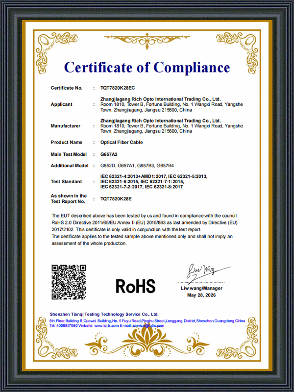
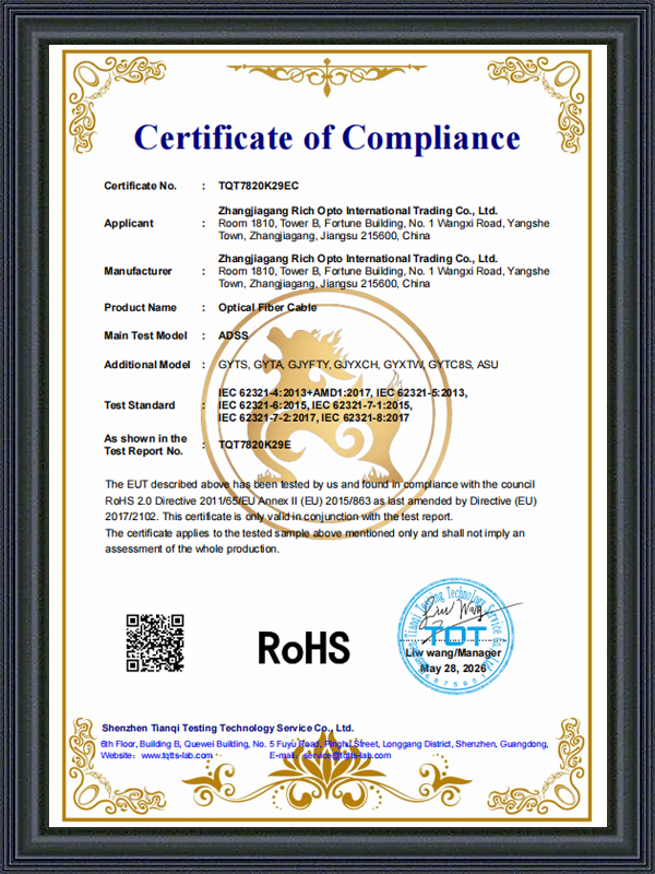
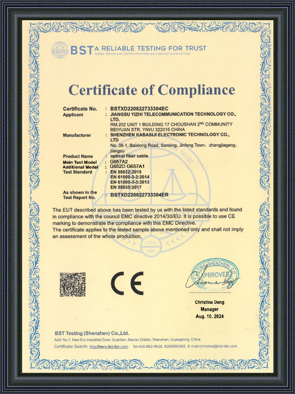
Certificate Of Honour
  • Certificate of Compliance
  • Certificate of Compliance
  • Certificate of Compliance
What’s News

Industry Insights and Updates